Strand7 API를 이용한 Steel Design software BCDsteel
페이지 정보

본문
Steel design software for Strand7 FEA
for AISC 360, AS 4100, EC3, NZS 3404
Overview
BCDsteel software is for the design of steel structures modelled with Strand7 FEA.
This checks members in accordance with US specification AISC 360-16 (LRFD and ASD),
Australian Standard AS 4100, Eurocode EC3, and New Zealand Standard NZS 3404.
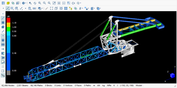
It uses the Strand7 API to display the model, using the normal Strand7 tools to control the view such as Dynamic Rotate,
Show or Hide Bricks/Plates/Links/Beams/Nodes, and Show or Hide Groups etc.
It analyses steel members that have been modeled using beam elements.
All other Strand7 features may be included in the model including links, plates and brick elements as well as multiple freedom cases,
stage analyses, groups, and tapered beam elements.
The model can be analysed with first or second order elastic global analyses.
In Strand7, these are the linear static solver or nonlinear static solver with nonlinear geometry.
The analyses use the highest tier equations for all codes when possible.
The program includes many “nice to have” features, ones that are often not available to engineers.
The tools provided are designed to minimise user input, and to provide output in a clear format that is ideal for design or for inclusion in reports.
BCDsteel is simple to use; it is self explanatory, and does everything well. And it is enjoyable to use!
BCDsteel has been developed independently of Strand7. The AS 4100 solver has been commercially available since 2011.
The EC3 solver was added April 2017, and the AISC 360 solver added June 2018.
Features
- All the information relevant to steel design is contained within the models data File.
This means a model analysed by one person can be re-analysed by someone else even if it includes non-standard materials or sections properties. - It is possible to have multiple copies of BCDsteel open at the same time, with a different model open in each.
- The program will automatically define members and restraints, based on the geometry of the structure and taking into account
- node restraints, beam end release, orientation / alignment etc. Tools are provided to manually over-ride these if necessary.
- BCDsteel places no limitations on the number of load cases / combinations or number of nodes / beam elements etc.
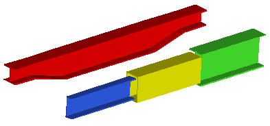
- The section property may vary along the length of a member, and the beam elements may be tapered or stepped as illustrated below here.

For AS 4100
- The section capacity of Slender sections is calculated for bending about both the major and minor principal axes.
- Star battened equal leg angle sections used for bracing are analysed to Clause 6.4.3.
- Equal leg angle web members in trusses can be analysed in accordance with Clause 8.4.6. This can result in significantly higher capacity than Clause 8.4.5.
- The calculation of out-of-plane capacity to Clause 8.4.4.1 uses the highest tier equation using a value of βm that is applicable to members
with transverse loads as well as no transverse loads. Details of the method of calculating βm are described in the Help file.
For EC3
- All section types supported by BCDsteel are analysed for Class 2 to 4. Class 1 is simply treated as Class 2.
The exception is Class 4 round hollow sections which are presently not supported. - For Class 2 sections, BCDsteel calculates an “exact” solution to (6.31) for all section types supported and for
any combination of N My Mz without needing to use the approximate equations in 6.2.9.1. - For 6.3.3 Bending and axial compression, Equations (6.61) and (6.62) are analysed using Annex B.
The advantage of Annex B is that it requires no user input - BCDsteel calculates all variables required.
Annex A is not available at this time.
For AISC 360
- The user can select either Load and Resistance Factor Design (LRFD) or Allowable Strength Design (ASD).
- The solver is intended for use with the Direct Analysis Method. Alternatively,
the Effective Length Method can be used for structures that satisfy the limitations specified in Appendix 7. - Ch E5(a), E5(b) is included as an option for equal leg angle compression members.
- Ch F buckling modification factor Cb includes equations in the commentary and the reference documents for
singly symmetric I-shapes in reverse curvature, and a load height factor for destabilizing loads.
For NZS 3404
- The solver is based on AS 4100 but includes a number of changes so that it complies with NZS 3404.
- A module is included to assist checking a structure to Section 12 Seismic design.
Compliance is checked for many clauses including some of the more onerous ones.
The graphics provide a simple effective way to document the design.
Sections analysed
The solvers will analyse all the section types shown below.
The major principal axis may be oriented either direction as indicated.

They include solid rectangular and solid round shapes, mirrored channels, star battened angles, and cruciform.
The pink and grey section is a boxed-in I-section that must be modelled as a BXS section. (Other BXS sections cannot be analysed).
The above figure shows a Box section with 1 internal stiffener per face. BCDsteel will analyse a Box section with
between 0 and 3 discontinuous longitudinal stiffeners per face as in the following figures:
For AS 4100 and NZS 3404, slenderness is taken into account for all section types for bending
about both principal axes and for axial compression.
The ineffective width is omitted from each “flat plate element” in accordance with Clauses 5.2.5 and 6.2.4.

For EC3, Class 4 section properties are calculated using the forces at each of 9 equi-spaced sections along
each member by omitting the ineffective widths in accordance with 5.5.2 and Table 5.2.
For AISC 360, slenderness is taken into account in accordance with Ch E – G. For stiffened Box sections,
reference is made to AASHTO LRFD Bridge Design Specifications.
With NZS 3404 Seismic design to Section 12, all section shapes are supported except for IBoxed sections and StiffenedBox.
댓글목록
등록된 댓글이 없습니다.

